Tech Portal
Tech Portal
Anatomy of a Machine Vision System
Overview
Even though the main component of every machine vision system is a camera, no machine vision system is complete without all of the following components:
- Lighting
- Lens
- Camera
- Cabling
- Interface Peripherals
- Computing Platforms
- Software
Each component in a machine vision system plays an important role in fulfilling the overall purpose of the system which is to help machines make better decisions by looking at the outside world. Fulfillment of this purpose requires orderly positioning of the components such that the flow of information starting from capturing of light to delivering and processing a digital image can be facilitated.
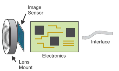
The following image shows the positioning of each component. Each component mentioned in the image is discussed in detail below.
Lighting
When a camera captures an image of an object, what it’s really doing is capturing the light that the object has reflected. The degree to which light is absorbed or reflected is dependent on the object’s surface whether it is transparent, translucent or opaque.
In order to make sure the camera is able to capture all the details required for analysis, machine vision systems need to be equipped with proper lighting. Various techniques for engineering lighting in a machine vision system are available based on the position, angle, reflective nature and color spectrum of the light source. These are:
- Position based lighting techniques
- Front lighting – Both the camera and light source are facing the target scene from the same side.
- Back lighting – Camera and light source are positioned opposite to each other with the target scene being in the middle.
- Front lighting – Both the camera and light source are facing the target scene from the same side.

- Angle based lighting techniques
-
- Directed lighting – A single light ray or a group of rays spread at a very narrow angle illuminates every point on the target scene. Directed lighting casts strong shadows and makes texture stand out in the image.
- Diffused lighting – Light rays spread at wide angles illuminates every point on the target scene. Diffuse lighting casts little to no shadows thus eliminating shading and making the texture more evident.
- Directed lighting – A single light ray or a group of rays spread at a very narrow angle illuminates every point on the target scene. Directed lighting casts strong shadows and makes texture stand out in the image.
-
-
- Axial diffuse lighting – A beam splitter reflects diffused light downwards on the target resulting in an even illumination.
-
-
-
- Diffused dome lighting – A mirror in the shape of a hemisphere reflects diffused light downwards illuminating the target.
-

- Reflective nature based lighting techniques
-
- Dark field illumination – Light source is positioned such that it’s light will not be reflected off a mirror or transmitted directly into the camera’s field of view.
-
- Bright field illumination – Light source is positioned such that it’s light is expected to be reflected off a mirror or transmitted directly into the camera’s field of view.

- Pattern based lighting technique
- Structured lighting – In the case of structured light, a light pattern such as dots, grids or a more complex shape is projected at an angle onto an object.
- Color spectrum based lighting techniques
-
- RGB lighting – For monochrome imaging, the light is usually a narrow band of wavelengths either red, or green, or blue.
-
- White lighting – For color imaging, white light is needed.
- Light spectrum based lighting techniques
-
- UV lighting – Ultraviolet (UV) is a spectrum of shorter wavelengths (200nm to 400nm) than those of visible light (400nm to 780nm). In the case of UV lighting, a source emitting UV light is used to illuminate an object.
-
- SWIR lighting – Shortwave Infrared (SWIR) spectrum (900 nm to 2,500 nm) is the region of infrared light (780 nm and 1 mm) closest to the visible light. In the case of SWIR lighting, a source emitting SWIR light is used to illuminate an object.
-
- NIR lighting – Near Infrared (NIR) wavelengths are in the range of 780-1400 nm. In the case of NIR lighting, a source emitting NIR light is used to illuminate an object.
Lens
A lens is a device that magnifies a scene by focusing the light entering through it. In simple words, a lens allows the camera to see the outside world clearly. A scene as seen by the camera is regarded as in focus if the edges appear sharp and out of focus if the edges appear blurry. It is important to note here that lenses used in machine vision cameras often have a fixed focus or adjustable focus whereas lenses used in consumer cameras for example DSLR and Point & Shoot cameras have auto-focus. Angle of View (AoV), Field of View (FoV), Object Distance, Focal Length, Aperture and F-Stop are some of the terms often used when categorizing lenses. Below is a brief explanation of these terms:
- Angle of View (AoV)
The Angle of View (AoV) refers to the angular extent of an area (in degrees) that can be viewed through the lens. AoV is a specification of all lenses which is derived by focusing a lens to infinity while using a compatible sensor size. For a given lens and a sensor size, AoV is constant.
- Field of View (FoV)
Field of View (FoV) refers to the rectangular extent of an area that can be viewed through the lens but FoV is dependent on the focal length and object distance. FoV describes what is captured at a specific focal length as opposed to focusing the lens to infinity in the case of AoV.
- Object Distance
Object distance is the working distance between the lens and the target object.
- Focal Length
The focal length is the distance between the lens and the focal point. When the focal point is on the sensor, the image is in focus.
- Aperture and F-Stop
The aperture is the opening of the lens which controls the amount of light reaching the sensor. The size of the aperture is measured by its F-stop value. A large F-stop value means a small aperture opening, and vice versa.


Types of lenses
1. Entocentric / Endocentric lens – These lenses come with a fixed focal length and are the most common lenses used in machine vision cameras.

2. Macro lens – Macro lenses are designed to achieve high magnifications and they generally work in the magnification range of .05x to 10x.

3. Telecentric lens – Telecentric lenses do not have an imaging angle and create a perpendicular view of the scene.

Camera
A protective case that contains a lens mount, an image sensor, a processor, power electronics and a communication interface is what is referred to as a camera in machine vision.
At the core of any camera lies an image sensor that converts incoming light (photons) into electrical signals (electrons). An image sensor is comprised of exposing arrays called “photodiodes” which act as a potential well where the electromagnetic energy from photons is converted into micro-voltage. This voltage is then passed to an Analogue-to-Digital Converter (ADC) which outputs a digital value. Image sensors available in the market can be categorized based on the physical structure (CCD/CMOS), pixel dimensions (Area Scan/Line Scan), chroma type (Color/Mono), shutter type (Global/Rolling), the light spectrum (UV/SWIR/NIR) and polarization of light.
Each photodiode on a sensor corresponds to a pixel of a digital image. While a photodiode is associated with the analog value, an image pixel is associated with the digital value. A pixel is the smallest element in a digital image and is an abbreviation of ‘picture element’. Resolution, intensity, exposure, gain and frame rate are some of the basic concepts related to digital imaging which are discussed below.
Digital image concepts
- Resolution – A digital image is made up of pixels. Image resolution is a measurement of the number of columns of pixels and rows of pixels in an image. An image resolution of 1280 x 1024 tells us that the image measures 1280 pixels in width and 1024 pixels in height.
![]()
- Intensity – The brightness of an image pixel is called intensity. The larger the bit-depth of an ADC, the bigger the range for expressing intensity. For example, if the bit-depth of an ADC is 8-bits, there are only 2⁸ or 256 (0 to 255) values available to express intensity. However, if the bit-depth of an ADC is 12-bits, there are now 2¹² or 4096 values available to express intensity.

- Exposure – Exposure refers to the duration of time during which a photodiode is exposed to light. Exposure time is typically measured in microseconds (µs) and milliseconds (ms).

- Gain – Gain is the amplification of the intensity values for pixels. When the strength of the photodiode charge is increased in the sensor, it is called analog gain and when the pixel value is increased after the charge has been converted into a digital value it is called digital gain.

- Frame rate – Frame rate measured in frames per second or FPS, is the number of images a sensor can output in one second.

Cabling
Ethernet
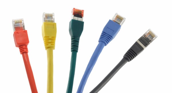
Ethernet is a Local Area Network (LAN) technology that was introduced in 1983 by the Institute for Electrical and Electronic Engineers (IEEE) as the 802.3 standard. IEEE 802.3 defines the specification for physical layer and data link layer’s media access control (MAC). Ethernet is a wired technology that supports twisted pair copper wiring (BASE-T) and fiber optic wiring (BASE-R). The following tables below mention various Ethernet networking technologies based on their speed and cable/transceiver type.
| Twisted pair copper wiring-based BASE-T Ethernet standards |
|---|
| Name | Speed | Cable Type | Max. Cable Length |
|---|---|---|---|
| 1000BASE-T | 1 Gbps | Cat5e Cat6 |
100 m |
| 10GBASE-T | 10 Gbps | Cat6A Cat7 Cat 7A |
100 m |
| Fiber optic wiring-based BASE-R Ethernet standards |
|---|
| Name | Speed | Transceiver Type | Max. Cable Length |
|---|---|---|---|
| 10GBASE-R | 10 Gbps | SFP+ (1 lane) | 80 km (ZR) |
| 25GBASE-R | 25 Gbps | SFP28 (1 lane) | 80 km (ZR) |
| 50GBASE-R | 50 Gbps | QSFP28 (2 lanes) SFP56 (1 lane) |
80 km (ZR) |
| 100GBASE-R | 100 Gbps | QSFP28 (4lanes) SFP56 (2 lanes) SFP-DD (2 lanes) |
80 km (ZR) |
| 200GBASE-R | 200 Gbps | QSFP56 (4 lanes) QSFP-DD (4 lanes) |
80 km (ZR) |
| 400GBASE-R | 400 Gbps | QSFP56 (8 lanes) QSFP-DD (8 lanes) |
80 km (ZR) |

Universal Serial Bus (USB)
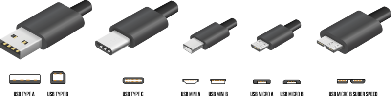
Universal Serial Bus (USB) standard was first released in 1996 and is maintained by the USB Implementers Forum (USB-IF). USB was designed to standardize the connection of peripherals to personal computers. USB can both communicate and supply electric power to peripherals such as keyboards, mouse, video cameras, and printers. The below table mentions various USB standards and their speeds.
| USB standards |
|---|
| Name | Speed | Maximum Cable Length |
|---|---|---|
| USB 2.0 | 480 Mbps | 5 m |
| USB 3.0 | 5 Gbps | 3 m |
| USB 3.1 Gen 1 | 5 Gbps | 3 m |
| USB 3.1 Gen 2 | 10 Gbps | 3 m |
| USB 3.2 (2 x 3.1 Gen 1) | 10 Gbps | 3 m |
| USB 3.2 (2 x 3.1 Gen 2) | 20 Gbps | 3 m |
| USB 4 | 40 Gbps | 0.8 m |
CoaXPress
CoaXPress(CXP) is a point‐to‐point communication standard for transmitting data over a coaxial cable. The CoaXPress standard was first unveiled at the 2008 Vision Show in Stuttgart and is currently maintained by the JIIA (Japan Industrial Imaging Association). Below table mentions various CXP standards.
| CoaXPress standards |
|---|
| Name | Speed | Max. Cable Length |
|---|---|---|
| CXP-1 | 1.25 Gbps | 212 m |
| CXP-6 | 6.25 Gbps | 60 m |
| CXP-12 | 12.5 Gbps | 40m |
| CXP-over-Fiber | 10 Gbps | 80 km |

Camera Link
Camera Link is a high bandwidth protocol built for parallel communication. It standardizes the connection between cameras and frame grabbers. Camera Link High-Speed (CLHS) evolved from Camera Link and was first introduced in 2012. It delivers low-latency, low-jitter, real-time signals between a camera and a frame grabber and can carry both the image and configuration data using for both copper and fiber cabling.
| Camera Link standards |
|---|
| Name | Speed | Max. Cable Length |
|---|---|---|
| Camera Link Base | 2.04 Gbps | 10 m |
| Camera Link Full | 5.44 Gbps | 10 m |
| Camera Link Deca | 6.80 Gbps | 10 m |
| Camera Link HS (High-Speed) | 25 Gbps | 80 km |

Interface Peripherals
Ethernet
- Network Interface Card (NICs) – An Ethernet network interface card (NIC) is an expansion card that connects to a computer motherboard over PCIe slot and implements the electronic circuitry for the physical layer and data link layer of the Open Systems Interconnection model (OSI model).

- Switches – A network switch connects Ethernet devices within the same Local Area Network (LAN). When a switch receives a packet from one of the devices connected to its physical ports, the switch reads its header, then matches the destination address or addresses and sends the packet out through the appropriate ports to the destination devices. Following are some of the machine vision camera features that require the use of a switch:
-
- Multiplexing – In high-speed multi-camera systems (for example 64 camera systems), where each camera is outputting large amounts of pixel data, switches are required to consolidate pixel data coming from multiple ethernet ports and output it to a server or host PC using a single port.
-
- Multicasting – Machine vision applications that use multicasting require a switch in order to send camera data to multiple host PCs.
-
- Precision Time Protocol (PTP) – A switch is a requirement if timestamps of multiple cameras need to be synchronized to a single device’s clock.
- Precision Time Protocol (PTP) – A switch is a requirement if timestamps of multiple cameras need to be synchronized to a single device’s clock.

- Ethernet Hubs – A hub can also connect several devices together for the purpose of sharing resources, and the collection of devices attached to a hub is known as a LAN segment. A hub differs from a switch in that packets sent from one of the connected devices are broadcast to all of the devices that are connected to the hub. With a switch, packets are directed only to the port that leads to the addressed device.

- Motherboard-Resident Ethernet Ports – These days all motherboards have built-in Ethernet ports that mainly support 1Gbps speeds and in some cases can also support 5Gbps and 10Gbps speeds. Built-in Ethernet ports on a motherboard are not recommended for high-speed applications because of their limited internal buffer size and limited performance.

Universal Serial Bus (USB)
- USB PCIe Cards – USB cards are PCIe based expansion cards that are used to increase the number of USB ports on a PC. A variety of USB cards are available in the market supporting various USB standards like USB 2.0 and USB 3.0 and supporting various USB connectors such as USB-A, USB-B, USB-C and Micro-USB.

- USB Port Hubs – USB hubs are external devices that connect to a computer using a male USB connector and have female USB ports available on it. USB hubs add additional USB ports to your computer, so you can plug in extra USB devices.

- Motherboard-Resident USB Ports – Most motherboards these days come with built-in USB 3.0 ports with some motherboards still supporting both USB 2.0 and USB 3.0.

CoaXPress
- Frame Grabbers – CoaXPress frame grabbers “grab” individual frames from a camera and enable a variety of high-end acquisition and image processing capabilities such as real-time compression, and the ability to offload Regions Of Interest (ROI) for additional bandwidth utilization.

Camera Link & CLHS
- Frame Grabbers – Similar to CoaXPress frame grabbers, Camera Link frame grabbers “grab” individual frames from a camera and include various onboard processing capabilities such as programmable region of interest, pixel decimation, image scaling, and lookup tables.

Computing Platforms
The processor inside a machine vision camera is usually an embedded processor or a field-programmable gate array (FPGA) which runs a model-specific firmware. This firmware is responsible for reading the pixel values from the image sensor, implementing image sensor features, processing pixel data to create a full image, applying image enhancement algorithms and communicating with external devices to output a complete image.
The processor inside a camera is constrained to minimize power consumption and reduce heat generation. As a result, it is limited in its processing capability when it comes to handling very high frame rates and outputting post-processed images at the same time. To post-process large amounts of image data coming from a very high frame rate sensor, it is preferred to send this data to an external system for processing instead of using resources from the camera processor. Various systems used in the post-processing of images are:
- Consumer PCs – Consumer PC-based systems are the most flexible and cheapest options as off-the-shelf components can be used to design a system. Machine vision cameras can be connected with PC-based systems using interfaces like Ethernet, USB, CoaXpress and Camera Link.

- Industrial PCs – Industrial PCs are built in a rugged casing to provide protection against dust and debris. These PCs can withstand shock, vibration and extreme temperatures in the industrial environment. Similar to Consumer PCs, cameras can also be connected to Industrial PCs using interfaces like Ethernet, USB, CoaXpress and Camera Link.

- Vision Controllers – Vision controllers are also PC-based systems but besides PC functionality, they also offer support for serial and I/O devices. Vision controllers come with built-in serial and I/O interfaces such as RS232/RS485 ports, Analog I/O and Digital I/O. Serial and I/O interfaces allow easier integration with programmable logic controllers (PLC) and industrial communication C Series modules and enable the implementation of communication protocols such as Modbus serial. Some vision controllers also have a PWM feature for controlling lighting. Most vision controllers have Ethernet and USB ports for connecting machine vision cameras.

- Embedded Systems – Embedded systems are highly configurable computers that are designed so they can be embedded in other larger systems like autonomous vehicles, drones and medical devices. Since these embedded systems also support the same standard interfaces like Ethernet and USB, they can be easily interfaced with machine vision cameras. Some examples of embedded systems are NVIDIA Jetson Orin and NVIDIA Jetson Xavier.

- Workstation PCs – Workstation PCs using processors like AMD Threadripper PRO or Intel i9 is the preferred choice for building multi-camera system when it comes to balancing performance with cost.

- Enterprise Servers – Enterprise Servers using processors like AMD EPYC and Intel Xeon can not only manage the distribution of pixel data from high-speed multi-camera systems to processing nodes but they also offer exceptional performance for image processing workloads.

- Cloud-based Systems – As the complexity of machine vision applications is increasing for example with the use of artificial intelligence, even PC-based systems are not able to fulfill the processing requirements in some cases. This is where cloud-based processing platforms like AWS, Azure and Google Cloud are filling the gap as they provide ample resources to scale processing.

Software
While a machine vision camera is responsible for capturing an image and sending it to the host PC, imaging software running on the host PC is responsible for:
-
- Interfacing with the camera hardware
- Controlling the camera features
- Receiving, processing and analyzing images
- Performing decision-making using image results
- Communicating with any other connected devices or machines that need camera input
The three categories of imaging software in machine vision are:
- Camera Viewer – Camera Viewer is the most user-friendly and interactive part of the imaging software which makes it easier to get started with a camera quickly. Besides network configuration, camera configuration, image capture, enhancement, display and recording functions, some imaging software also offer advanced tools for analyzing images such as histograms and line plots.

- Comprehensive Software – In addition to all the features of a Camera Viewer, a Comprehensive Software offers advanced features such as project management, multi-camera configuration, multi-server configuration, GPU support, 3D image reconstruction and 3D object viewer.

- Software Development Kit (SDK) – SDK is a collection of code samples, code libraries, application programming interface (API), documentation and compliers/debuggers etc. Most machine vision SDKs support C/C++/C#/Python programming languages and can be used to develop custom applications for Windows, Linux and ARM platforms.
