Tech Portal
Performance Line Scan Cameras, Software, and Systems for AI and Machine Learning Applications
Line-Scan Cameras
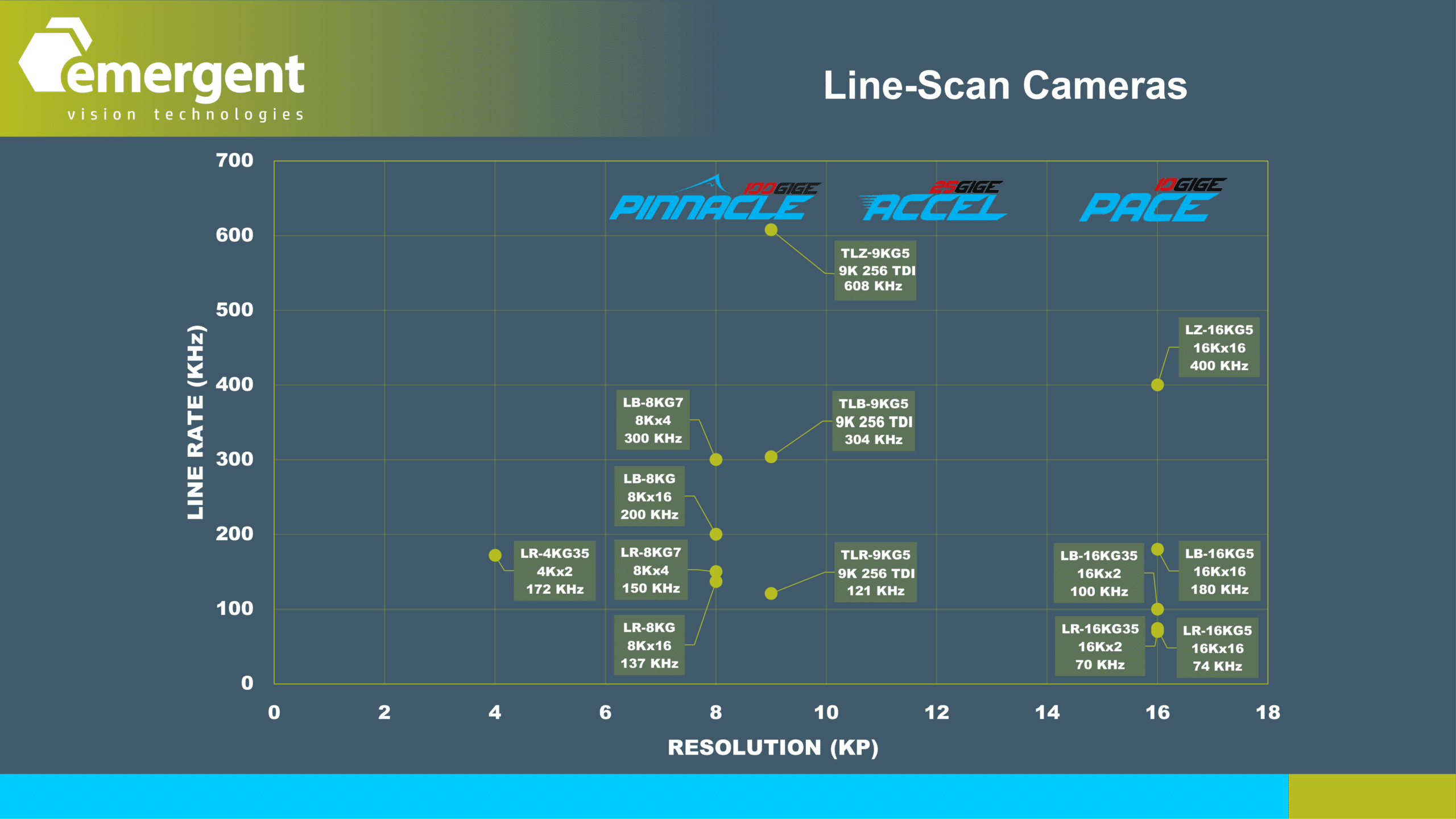
For line scan, the products range from 4K @ 172KHz up to 16K @ 400KHz with a special nod to 9K TDI @ 600KHz.
Full Featured
4K up to 16K
Highest Possible Line Rates
ie. 4K @ 172KHz, 16K @ 400KHz
Encoder Support
TDI
10GigE, 25GigE, 100GigE
Available now or Coming Soon!
Emergent line scan cameras are best known for covering an extremely wide range of resolutions and line rates. We incorporate all the best sensors from Gpixel. Gpixel boasts high image quality with resolutions and line rates that push Emergent 100GigE Pinnacle series to its limit. Emergent 25GigE Accel and 10GigE Pace models nicely round out the line scan product portfolio. Eros 5GigE cameras will join the line up in 2024 with smaller resolution models like 2K and 4K.


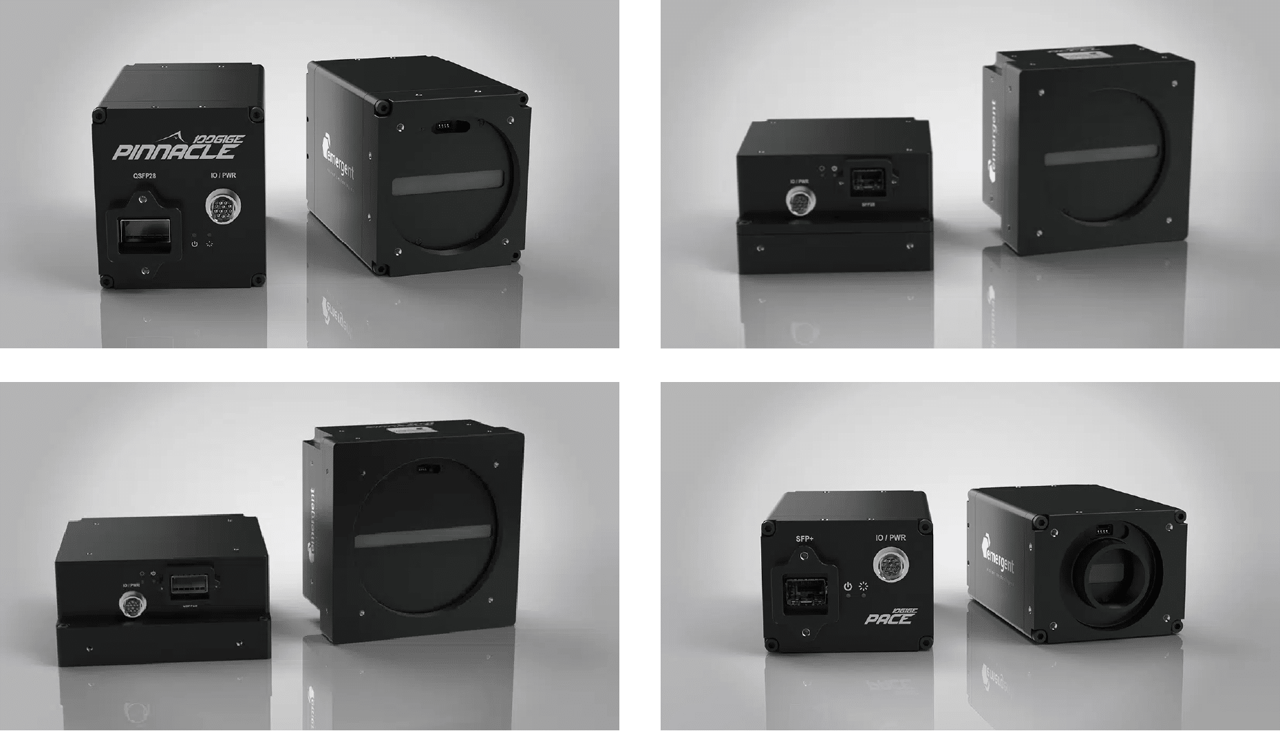
Figure: Emergent Line-Scan Cameras (100GigE Pinnacle, 25 GigE Accel, 10GigE Pace)
This animation illustrates the same task with a line scan camera. Generally, line scan cameras are used for scanning a continuous web of material like print or fabric but does not preclude applications as shown here with discrete objects. The cameras images here are hardware triggered by the sensor looking for objects on the conveyor. The individual lines of a given frame are triggered synchronously through the use of the continuous encoder signal shown in green. The lines of a given image are immediately transmitted back to the computer and assembled in the user buffer with zero copy technology. Emergent Line Scan cameras have encoder RS422 A/B inputs, 1 trigger input and 2 outputs.
TDI Line Scan Cameras are used to expose the same line
on the object multiple times to allow either higher speeds
with same lighting or same speed with lower lighting brightness requirement. TDI achieves this by having multiple lines in the sensor with each line exposing multiple times and the exposure or line rate is perfectly synchronized to the movement of the conveyor through the use of the encoder.
Line Scan IO
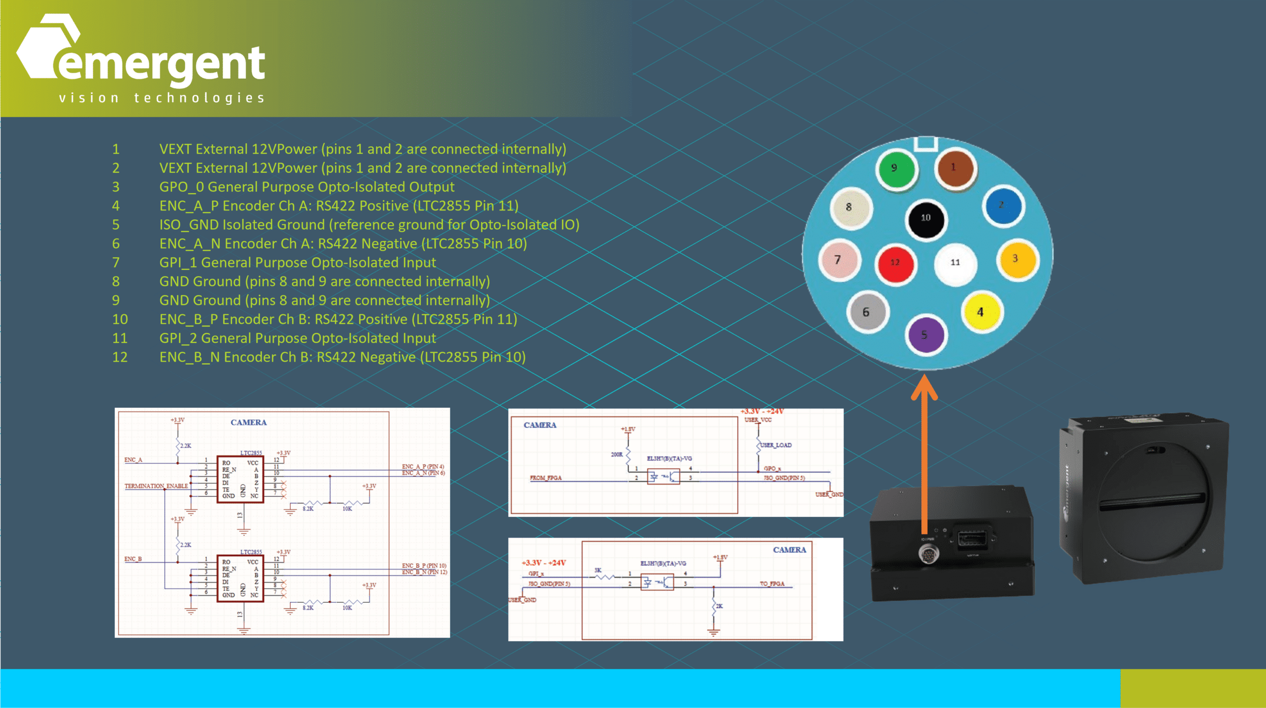
The IO connector of the cameras which is a 12 pin connector featuring differential quadrature encoder inputs as well as other general purpose inputs and outputs.
Triggering Options
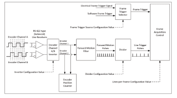
Here we see the general block diagram of the triggering options of the line scan cameras. Many modes are supported which vary from full internal based triggering to full encoder based triggering for precise synchronization with moving conveyor systems.
MODE A – All internal triggering
- LineTime parameter to control start of each line.
- FrameRate parameter to control start of each frame.
- FR_LT_Sync parameter to auto adjust LineTime given FrameRate.
MODE B – External Frame Trigger
- LineTime parameter to control start of each line.
- Hardware trigger to control start of each frame.
MODE C – External Frame Trigger, Encoder line time trigger
- Encoder to control start of each line.
- Hardware trigger to control start of each frame.
MODE D – Encoder Frame Trigger, Encoder line time trigger
- Encoder to control start of each line.
- Encoder to control start of each frame.
MODE E – External Trigger mask/pulse, Encoder line time trigger
- Encoder to control start of each line.
- Hardware input pulse to enable/mask line/frame generation.
Line Scan Parameters
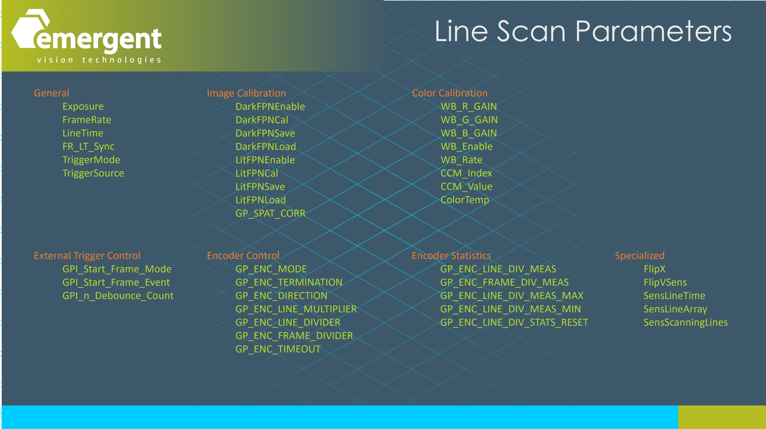
Here we see the subset of camera parameters specific to line scan camera operation which fall into categories such as: General purpose, Image Calibration, Color Calibration, External trigger control, Encoder control, Encoder statistics, and Specialized.
Dark/Lit FPN Correction
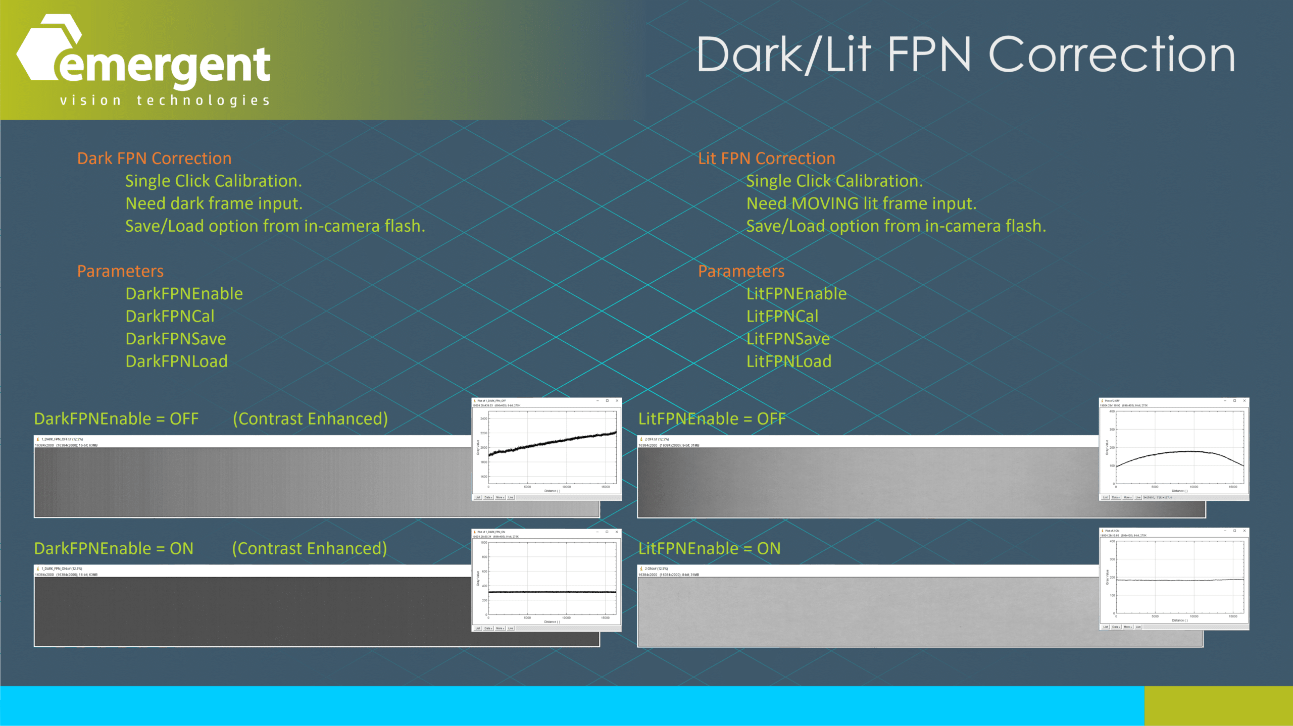
A line scan fundamental is Dark and Lit FPN calibration which falls under our Image Calibration category. On the left we see (contrast enhanced) dark images before and after dark FPN calibration. On the right we see lit images before and after lit FPN calibration. The graphs shown illustrate column averages which highlight the superb correction that the camera performs with a single click. The calibration curves can be saved and loaded to eliminate the need to recalibrate when powering up the system.
Mode D – Encoder Input

Our line scan cameras support quadrature encoder A and B inputs which allow the camera firmware to detect forward and backward motion by tracking the four encoder phases. With Mode D configured as shown, we can then set the GP_ENCODER_DIRECTION parameter to allow filtering in of only forward or backward pulses.
MODE D – Configuration
- TriggerMode = On
- TriggerSource = Hardware
- GP_ENC_MODE = On
- GP_ENC_TERMINATION = Off/On
- GP_ENC_DIRECTION = FWD/BWD
- GPI_Start_Frame_Mode = N/A
- GPI_Start_Frame_Event = Encoder_Frame_Divider
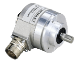
Mode D – Encoder
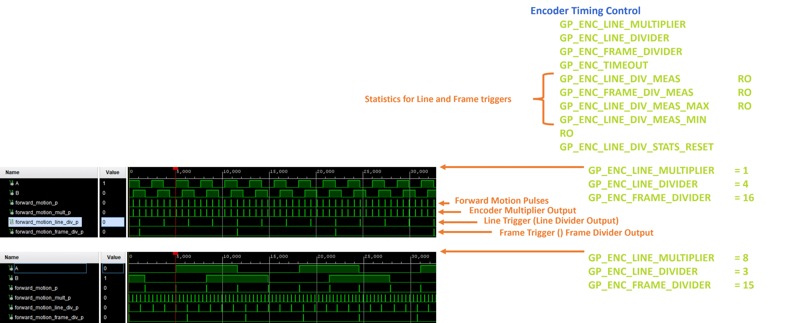
Additional camera firmware encoder features include an encoder pulse multiplier and an encoder pulse divider which are used to synchronize the material movement with the line triggers which can vary based on encoder model and magnification for example. We also provide statistics counters to allow system integrators to validate the triggers post multiplier and divider to check trigger rate and jitter characteristics.
Mode D – Encoder Divider Exercise
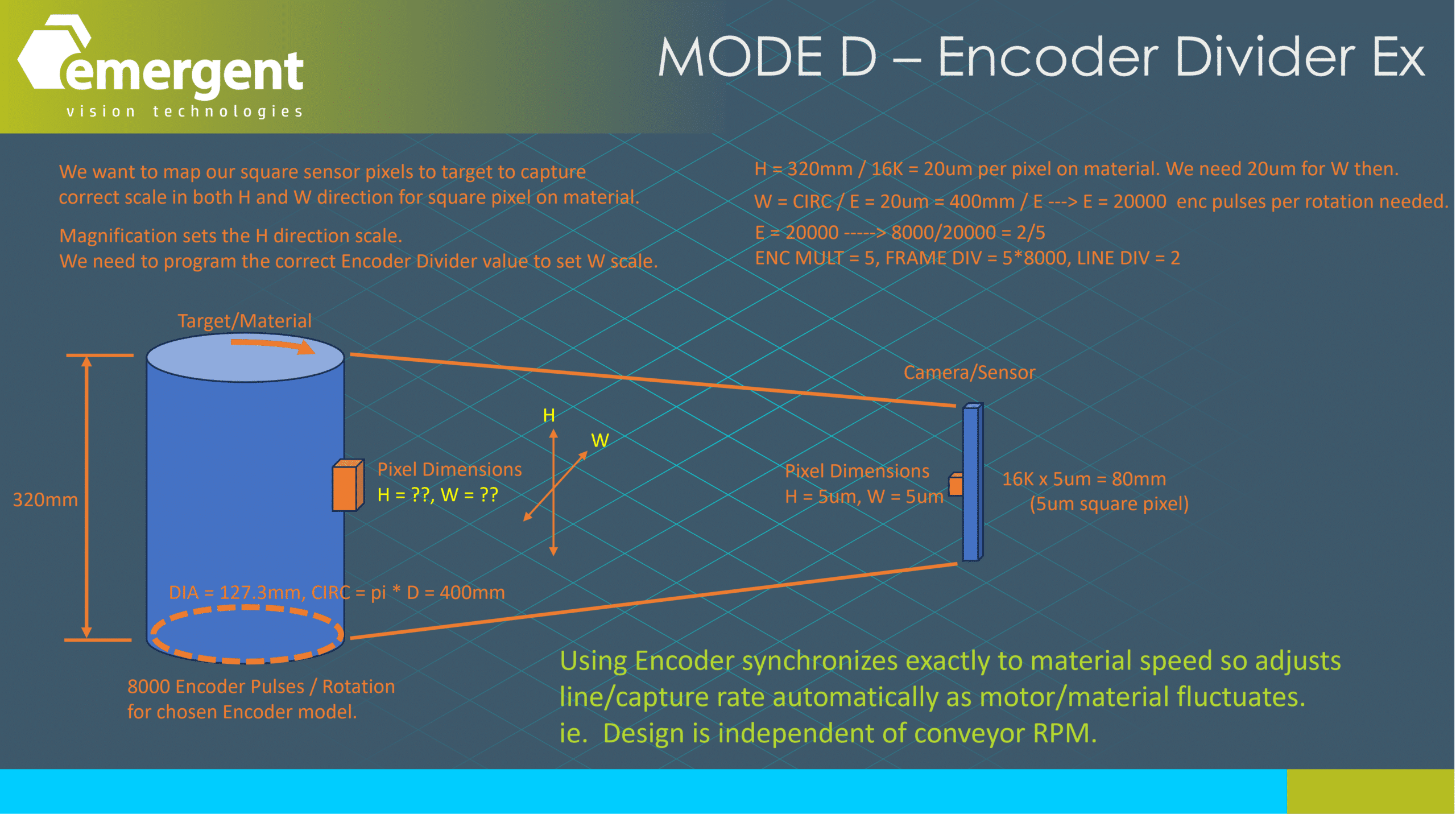
A fundamental exercise in line scan systems is to configure the scan rate to create the correct aspect ratio of the pixel.
In Mode A which is an all internal triggering method, we use the LineTime parameter and simply adjust the line time until the approximately correct height and width aspect ratio is observed – we can calculate this as well of course.
Note that this LineTime parameter does not track changes in material speed so the user must take care of this if correct image proportions are desired. In Mode D which is an all encoder triggering method, we need to set the encoder divider to the appropriate value to correct image proportions. This method is popular since it does track material speed without any runtime adjustments.
Mode D – Spatial Correction
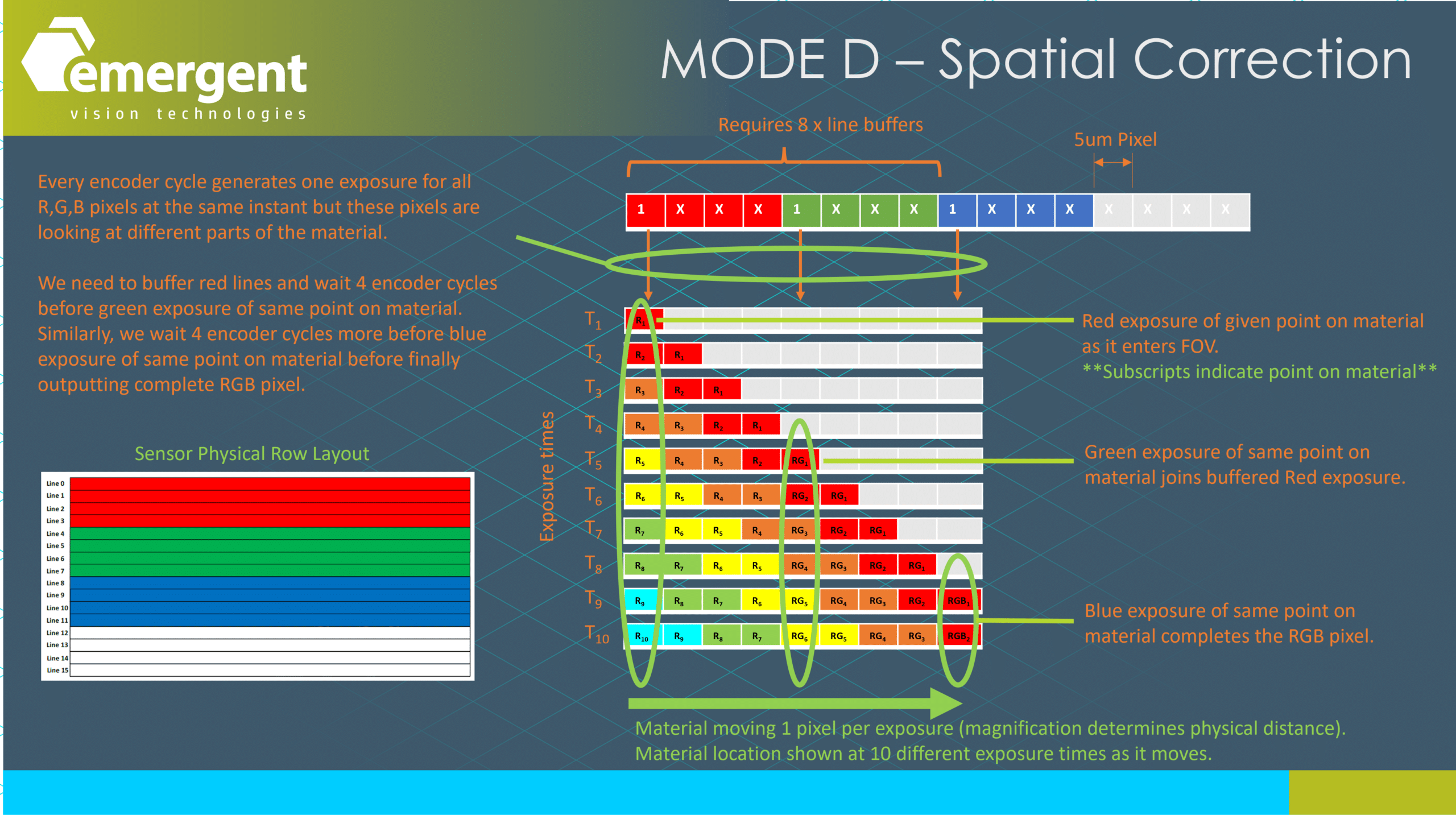
Unlike color area scan sensors which typically use a tight 2×2 bayer pattern and a debayering process involving approximation through interpolation, color line scan sensors such as the one shown here have a much greater seperation in the red, green, and blue channels. Every encoder cycle generates one exposure for all R,G,B pixels at the same instant but these pixels are looking at different parts of the material. We need to buffer red lines and wait 4 encoder cycles before green exposure of same point on material. Similarly, we wait 4 encoder cycles more before blue exposure of same point on material before finally outputting complete RGB pixel.
Specialized Parameters
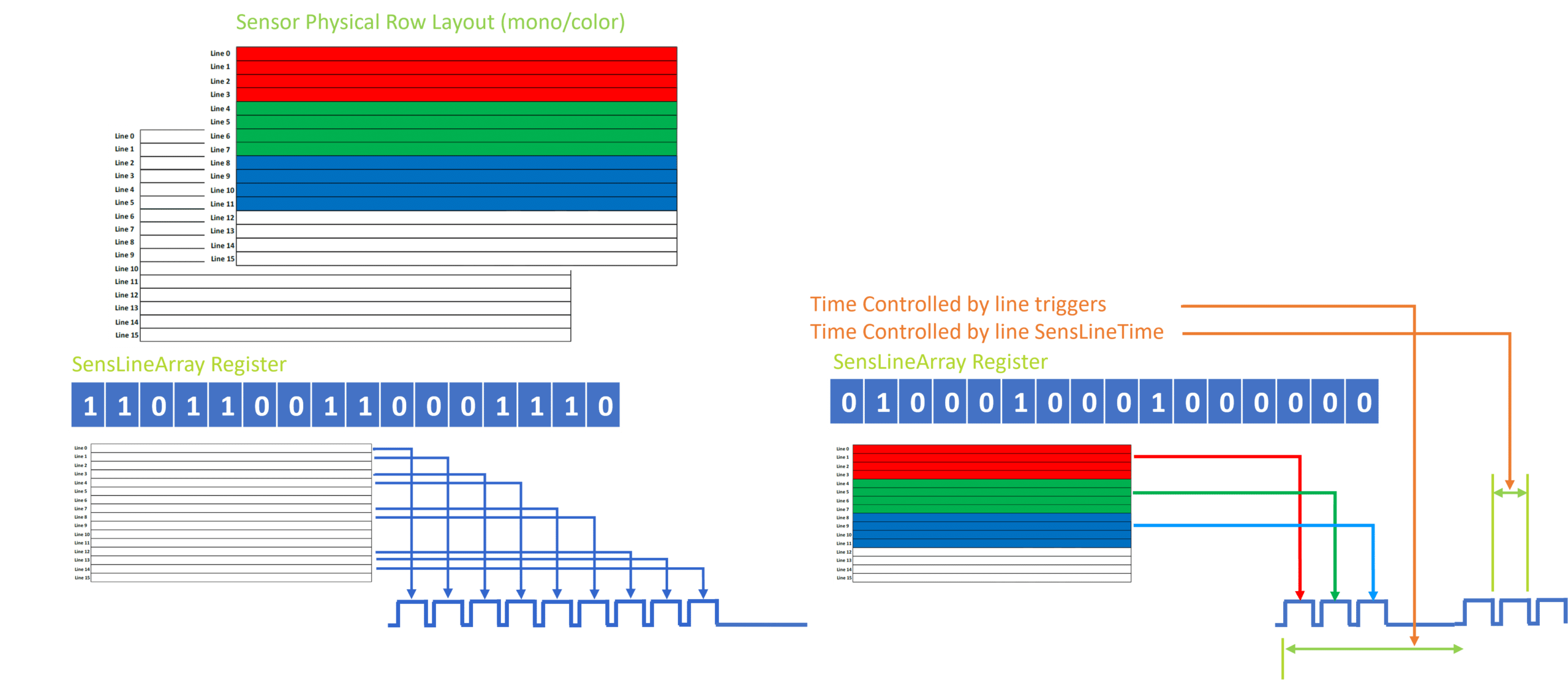
The GPixel GL5016 16K 5um 400KHz line scan sensor which we ship in the Emergent Pinnacle LZ-16KG5 100GigE line scan camera has special capabilities to output arbitrary rows of the 16 row sensor for specialized operations. Most commonly this is used for color imaging as shown on the right where we grab 1 red, 1 green, and 1 blue line and then employ spatial correction as previously shown as well as employing color calibration using the cameras white balance and color correction matrix features to create a best in class color image scan. We note that with this trilinear operation that there is no approximation through interpolation like color area scan bayer cameras so the color reproduction is optimal.

About Emergent Vision Technologies

Here is a recap of what Emergent is all about…
- 10+ Awards for innovation and pioneering the high speed GigEVision imaging movement
- 10+ years shipping 10GigE cameras with more than 140 models
- 5+ years shipping 25GigE cameras with more than 55 models
- 2+ years shipping 100GigE cameras with more than 16 models
- Camera technology performance leader
- Focused on high-speed Ethernet/GigEVision
- Focused on enabling the processing of high-speed image data
- Area scan and Line scan models
- UV, NIR, Polarized, Color, Mono models for multispectral applications
- Emergent eSDK for full application flexibility
- Emergent eCapture Pro for a highly comprehensive software solution
- Most comprehensive range of product and support for high-speed imaging applications
- Any speed, any resolution, any cable length
- Available NOW!
We are a multi-award winning company with a focus on high speed GigEVision product.
We have many years shipping product ranging in speeds from 10GigE up to 100GigE.
We have a strong focus on providing end-to-end technologies and support for our customers applications.
We can fullfil most application needs.
Lastly, products presented are available now.
Adoption of 10GigEVision and Higher
Here is a quick snapshot of the adoption of GigEVision products ranging in speeds from 10GigE up to 100GigE. Emergent has shown how top performance can be achieved and opened up many markets including machine vision to the use of such technologies. Some companies are just now leveraging our efforts toward releasing 25G and higher speed products but still a ways to go to release ratified and performance products.
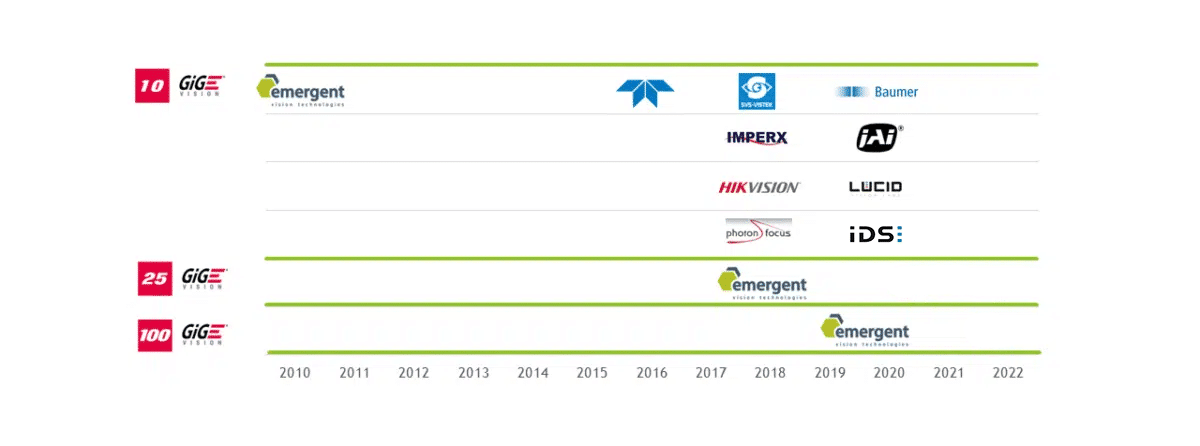
Figure: Emergent Vision Technologies is the first provider of cameras based on 10GigE, 25GigE, 50GigE, and 100GigE interfaces.

